Overview:
This page contains instructions on how perform an InfraRed (IR) remote control upfit on DishNetwork receivers that receive only Radio Frequency (RF / UHF) remote control commands. This allows a universal remote to be used to control the receiver instead of being required to use the standard remote. These instructions pertain to the following receivers:
Brands from: DishNetwork / Echostar / HTS / JVC
Receivers based on the: 4000 / 4500 / older 5000 / older 2000 “Deluxe”
These models receive only UHF remote signals. Note: The modified receiver will still work with the original UHF remote control as well as an IR remote control at the same time.
Note: Mixed results have been reported on successfully upfitting on a Model 2000 non-deluxe.
| Model 40xx, 41xx, 42xx, 45xx: Your receiver does not have IR capability. |
| Model 5000 Receivers: You can tell if your model 5000 receiver has the IR components based on the serial number of the receiver. BTFxxxxx and earlier receivers are UHF only and the IR Upfit will need to be performed. BTGxxxxx may or may not require the IR upfit components. BTHxxxxx and later receivers IR components already installed, giving it both IR and UHF capability by default. |
| Model 4700 and 4900 Receivers: These receivers already have the IR receiver installed. No modifications or programming is required on these receivers. |
| JVC HM-DSR100U D-VHS Receivers: This modification does not work on the these receivers. Search this website for appropriate instructions to modify your HM-DSR100U. |
UHF Remote TIP: If you are having trouble with UHF remote control reception, try relocating the antenna away from all electronic equipment. This can be done by using piece of coax cable, preferably RG6 or better, that is about 6 feet long.
Notes/cautions:
- Don’t perform this modification unless you are comfortable with electronics and a soldering iron.
- Doing this modification will double plus super extra void your warranty.
- If you blow something up, don’t blame me. It works on mine and on many other people’s receivers. There is no guarantee that it will work on yours.
- I don’t have any 4000 schematics or in-depth knowledge of the rest of the receiver, just the front IR panel.
- IR is an unsupported function on 4000’s and could disappear with any software update. Hopefully, the more modified machines there are out there, the less chance there is of this happening.
- I am in no way affiliated with Echostar. I am simply a customer who needed this function and had the information on how to do the modification.
- Read these instructions through at least once before doing anything.
- Make sure the receiver is powered off, unplugged, card removed, etc.
- If you have one of the unusual 4000 receivers with an IR input jack on the back panel, you can simply plug in a Xantec IR module or connect a stereo mini-plug cable to a device (audio receiver) with an IR output port.
Credits:
These instructions are based on a information posted by Sean Curtin in the alt.dbs.echostar newsgroup. That post was produced with the help of Todd Allcock and is based on the original post by nilavan @home.com. The post on which this page is based is archived at DejaNews at http://www.dejanews.com/getdoc.xp?AN=388634019 Also, thanks to Jeff Kane, John-Paul Andreini, Larry Lavoie, Barry Strittmatter, Todd Warnock, Terry Jenkins, Marshal Kendziorek, Anthony Fonzo, Davis White, Tom Kearney, Todd Allcock, Jeremey Mercer, Robert LeBlanc, and Martin Schuessler for their additional volunteered input.
Parts:
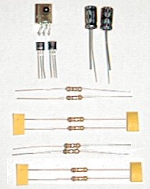
Parts Lists and Sources:
DigiKey:
| Part | Part # | Price | Notes |
| IR receiver | 425-1146-ND | $2.00 | Sharp GP1UM27XK. The leads are in the correct positions. |
| -or- IR receiver | 425-1144-ND | $2.00 | Sharp GP1UM277XK. The leads are in the correct positions. |
| -or- IR receiver | 4425-1122-ND | $2.00 | Sharp GP1UD277XK. The leads are in the correct positions. |
| IR receiver | 425-1122-ND |
$2.00 | No longer available. The leads are in the correct positions. |
| IR receiver, 56.8 kHz side-look | 160-1165-ND | $2.50 each | No longer available. Leads must be bent to convert to top-look version |
| IR receiver, 56.8 kHz top-look | 160-1160-ND | discontinued but still in stock | No longer available. .49″L x .41″W x .18″H+.28″ Leads) |
| 100uf radial aluminum electrolytic capacitor, 16 v | P5152-ND | $.28 each | Was part number P6227-ND |
| 22k ohm resistor, 1/4 W | 22KQBK-ND | $.28 per 5 | |
| 47k ohm resistor, 1/4 W | 47KQBK-ND | $.28 per 5 | |
| 10 ohm resistor, 1/4 W | 10QBK-ND | $.28 per 5 | |
| Transistor – general purpose | PN2907-ND | $.32 each | |
| 10k ohm resistor, 1/4 W | 10KQBK-ND | $.28 per 5 | not required on all systems |
| $5 charge for order less than $25 | $5.00 | ||
| Total | $10.00 |
Allcorp: (easiest-to-install IR receiver – external mount)
| Part | Part # | Price | Notes |
| External IR receiver | IRD-8 | $2.50 each | Enclosed IR receiver with 6′ cord and 3.5 mm stereo plug. Will not fit internally on circuit board (Sharp GPU57X) |
| IR receiver | IRD-6 | $2.50 each | No longer available. Enclosed IR receiver with 6′ cord and 3.5 mm stereo plug. Will not fit internally on circuit board (Sharp GPU57X) |
| -or- IR receiver | IRD-7 | $1.00 each | No longer available. should fit internally (Sharp GPU152Y — .59″Lx.59W”x.52″H) |
| 3.5 mm stereo jack | SJW-2 | $0.35 | 3.5 mm jack into which the IRD-6 can be plugged. You will need to drill a hole in the back of the satellite case to mount this component. (Should be compatible with Xantec controllers as well.) |
| 100uf capacitor, 16 v | 100/16VR | $.20 each | |
| 22k ohm resistor, 1/2 W | 22K-1/2 | $.50 per 10 | |
| 47k ohm resistor, 1/2 W | 47K-1/2 | $.50 per 10 | |
| 10 ohm resistor, 1/2 W | 10-1/2 | $.50 per 10 | |
| Transistor – general purpose | PN2907 | $.75 per 5 | |
| 10k ohm resistor, 1/2 W | 10K-1/2 | $.50 per 10 | not required on all systems but order one just in case |
| Shipping | $5.00 | ||
| Total | $8.95 |
Jameco:
| Part | Part # | Price | Notes |
| IR receiver | 139889 | $2.95 each | No longer available. Will barely fit internally. |
| 100uf radial aluminum electrolytic capacitor, 16 v | $.29 each | requires radial capacitor | |
| 22k ohm resistor, 1/4 W | 30453 | $.89 per 100 | |
| 47k ohm resistor, 1/4 W | 31149 | $.89 per 100 | |
| 10 ohm resistor, 1/4 W, carbon film | 29882 | $.89 per 100 | |
| Transistor – general purpose – 2N2907A | 38279 | $.35 each | |
| 10k ohm resistor, 1/4 W | 29911 | $.89 per 100 | not required on all systems |
| $20 minimum order, buy something else! | $12.85 | ||
| Shipping | $5.50 | ||
| Total | $25.00 |
Philips:
A small IR module (smaller than either of the other two options) is available from Phillips, replacement part # 483531057426. It fits much better than the Jameco module. The Vcc and Data pins will need to be switched. Pringle Electronic Distributors sells this part but they are not really set up for direct sales. They usually just supply electronics stores, but you can give them a try.
Pringle Electronic Dist Inc
1021 N Broadway
Everett, WA 98201
(425) 258-6161
Parts Notes:
IR Receiver Notes:
Using a Philips Pronto remote control, the Pronto Edit Software, and the “Pronto learned code display format document“, I found that the IR carrier frequency used by DishNetwork remote controls is 57.6 kHz. This is the optimum IR receiver frequency, however, other lower frequency receivers have proven to work just as well.
- DigiKey carries an IR receiver that can be adapted for this application. The DigiKey IR receiver is listed at 56.8 kHz, which is about the Dish remote uses. It has been verified that this IR receiver does work and that the pins are correctly oriented, requiring no lead switching.
- NOTE: The direct replacement, top-look receiver is no longer available from DigiKey. However, a corresponding side-look receiver is available. You must bend the leads with needle-nose pliers to convert the side-look to a top-look configuration.
- When I performed my first upfit, I ordered all of the parts from All Electronics Corporation ( http://www.allcorp.com / 1-800-826-5432 ). The IRD-6 IR receiver they sell is too large to fit internally in the receiver, even when removed from the plastic housing. I left mine in the plastic housing and mounted it externally as opposed to drilling a hole in the face of the satellite receiver. Another receiver that they sell, the IRD-7, is small enough for internal mounting but it does not have the correct pin orientation.
- I have been told that Jameco ( https://www.jameco.com / 1-800-831-4242 ) sells an IR receiver which is close to the correct size for internal mounting but has the 5V and data out pins switched.
- The IR receiver that Radio Shack sells is not 100% reliable in this application. It may or may not work for you; most people report poor range.
- The IR receiver installed at the factory is a Sharp GP1U27X. This is “generic” version that can use about any remote carrier frequency (it has a band pass center frequency of 40 kHz). For a slight increase in IR remote control range with EchoStar products, I would suggest the Sharp GP1U277X, but this part has proven to be impossible to find. It is identical except for having a band pass center frequency of 56.8 kHz, which is a closer match for the IR carrier frequency used by the remote control. I would assume the sales volume on the 277X is much lower than the 27X so it will probably cost a few pennies more if you can find them. The increased cost and low volume is most likely why EchoStar doesn’t use the 277X. I don’t know where to purchase either part in a small quantity but you can find a listing of Sharp distributors at http://www.sharpmeg.com/sharp/sales.html. The Adobe Acrobat file from the Sharp website detailing their IR receivers is available here.
Resistor Notes: All resistors can be either 1/4 or 1/2 watt.
Transistor Notes: Some aliases for the PN2907 transistor are MPS2907, 2N2907, ECG159, and NTE159. A 2N2907A transistor with a TO-18 metal case can also be used; as always, the metal tab on the side of the case denotes the emitter (labeled as “E” in the circuit diagram at the bottom of the page) and will point toward the IR receiver when installed on circuit board style A.
Capacitor Notes: As long as the voltage rating on the capacitor is greater that 5V, you’re okay. It doesn’t have to be specifically 16V. Keep in mind, however, that the larger the voltage rating for a electrolytic capacitor, the larger the physical size. If the capacitor is too tall, you will have problems snapping the daughter card back into the front panel.
Recommended tools:
- Philips screwdriver.
- Vice grips –or- drill and small drill bits –or- hack saw -or- a 0.035-inch thick piece of metal such a feeler gauge (for gaining access to the inside of the receiver)
- Soldering iron and solder (any soldering iron will work, I really like the 40 watt unit I purchased from AllCorp.com. The small extension tip I ordered makes the soldering easier. Also, I recommend using the smallest diameter/gage of solder you can find.)
- Wire cutters (for snipping off leads)
- Needle-nose pliers (for bending leads)
- De-soldering iron, de-solder wick / braid, or de-solder bulb / pump (optional, usually not needed)
- Multi-meter / Ohm-meter (optional but highly recommended for circuit continuity checking)
Disassembly:
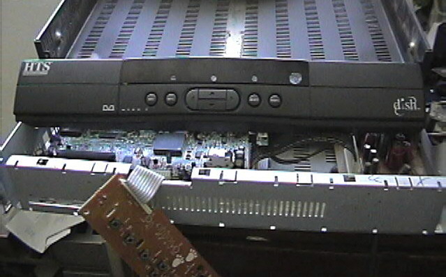
The cover is held on by 2 philips screws on the left and right sides as well as two on the back. It is also held on by 2 security screws on the upper-back, shown in the picture below. These can be removed by a good pair of Vice-grips; the needle nose style seems to work best. The second option for removing the security screws is to take a hack saw or Dremel tool and carefully cut a slot into the screw head and then use a flat head screw driver to remove them. The third option is to drill out the security screws with a very small diameter drill bit. If you choose this method, be sure to cover the top of the receiver to prevent metal shavings from falling through the slots.
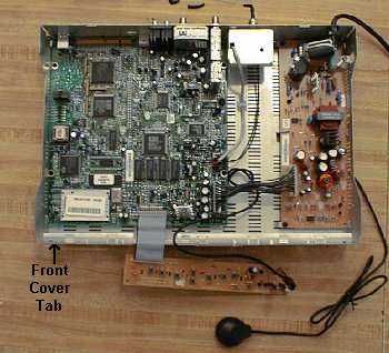
Once all screws are out, push the lid horizontally toward the back of the unit and lift it off. The plastic front panel and circuit board therein simply snap on/off via plastic tabs. Disconnect the flat cable by pulling from the sides, NOT the cable itself. The cable is difficult to remove — pliers are recommended. Pull firmly on edges of the cable so as not to bend the pins when the cable slides off the board.
It is also possible to remove the front cover without removing the case (or security screws) by unlatching the front cover tabs. The approximate location of the lower left tab is shown in the picture below, the tab extends and latches on the inside of the case. To remove the front cover insert a small, flat object (such as a 0.035-inch feeler gauge or thin Popsicle stick) in the top air vents near the front panel and push down on the bottom tabs just enough to unhook them. First one side and then the other. Next pull the front cover forward a little, push up slightly, and then pull forward to remove. To reassemble, push the top tabs in first then the bottom tabs. You will need to remove the daughter card from the front panel. This technique doesn’t work as well on model 2000 or older units because the tabs are much less flexible and can break off (the tabs can be epoxied back on).
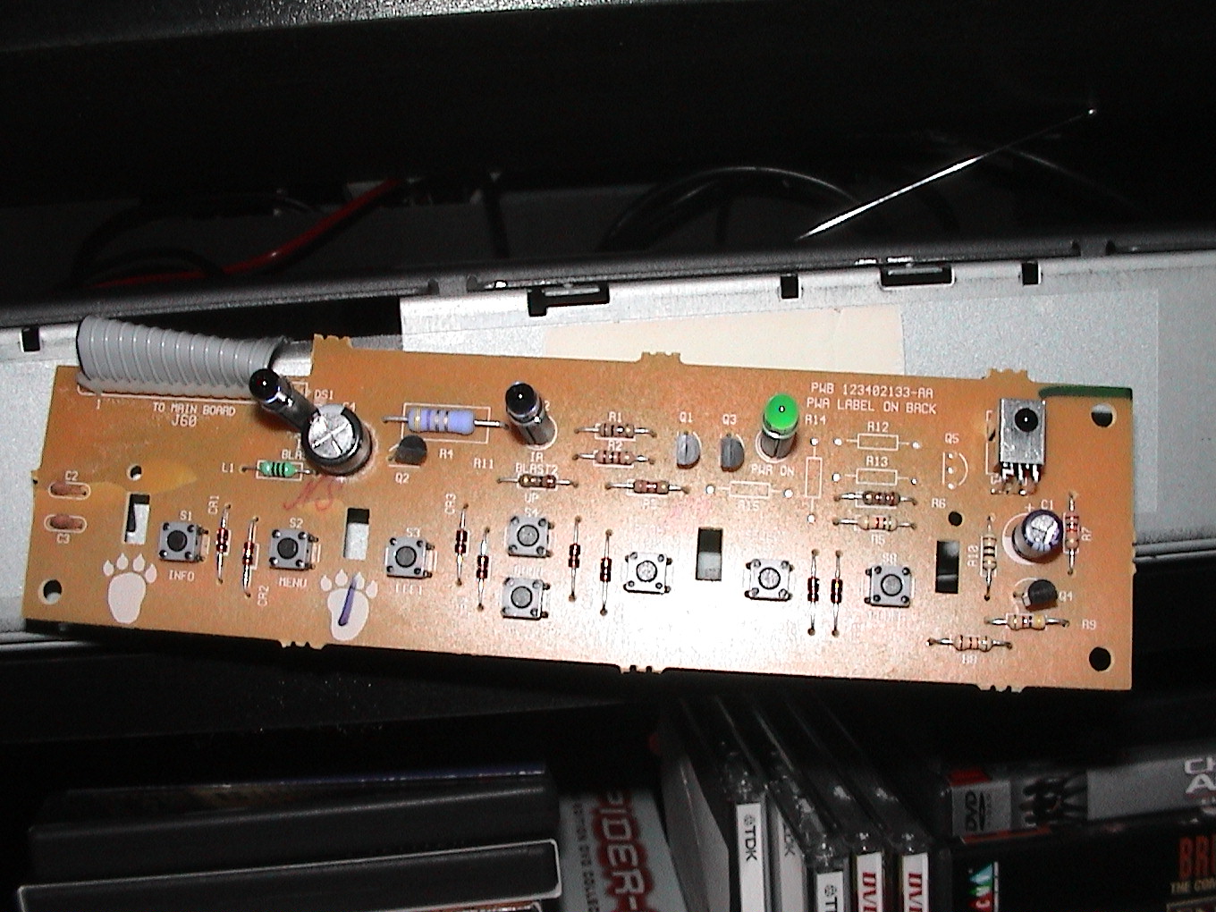
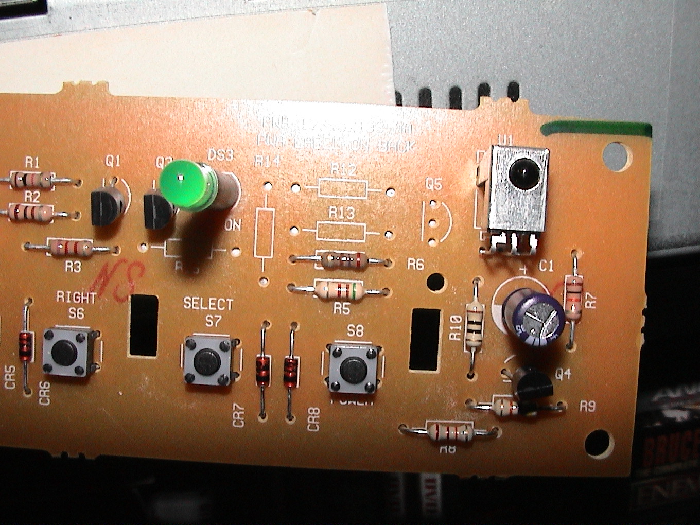
Identification of the electronics:
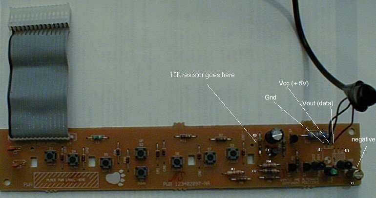
There are at least 3 different styles of 4000 front panel, each with a slightly different circuit board. If your 4000 has a small oval-shaped window where the power LED is located, you probably have style A. If your 4000 has a large, slightly curved window covering the entire upper center of the front face, you have style B. It is rumored that all JVC receivers are style B. The third style is something of a mystery. Many people seem to have it and the required parts are the same, however the silk-screened part designations (U1, C1, etc.) are at least partially different. If one of the component designations listed below doesn’t completely match up with vacant spaces on your board, you have style C. Style C owners will have to compare the openings on their circuit board with the circuit diagram at the bottom of the page to determine appropriate placement. Rest assured, however, that the parts listed below are necessary in all cases, only the designation changes.For 2000 Deluxe receivers, use the upper mounting location to match the pins of the DigiKey IR receiver.
These are the components of the front panel daughterboard. No modifications need to be made to the main board.
Style A:
U1………..Integrated IR receiver module
Q1………..PN2907 transistor
C1………..100uf 16V electrolytic capacitor
R1………..22k ohm resistor
R2………..10 ohm resistor
R3………..10k ohm resistor
R4………..47k ohm resistor
Style B: (HTS-branded units, possibly others)
U1………..Integrated IR receiver module
Q4………..PN2907 transistor
C1………..100uf 16V electrolytic capacitor
R7………..10k-ohm resistor
R8………..22k-ohm resistor
R9………..47k-ohm resistor
R10……….10 ohm resistorSome Philips Magnavox 4000 series Echostar receiver:
C3………..100uF- Slot C3 on the board
R11………10 ohm
R7………..47k ohm
R8………..22k ohm
Q3………..2N2907
R9………..10k ohm
Pictures of 4000 Board


Express View Model 4500 Circuit Board Pictures
HTS Model 3200 Circuit Board Pictures

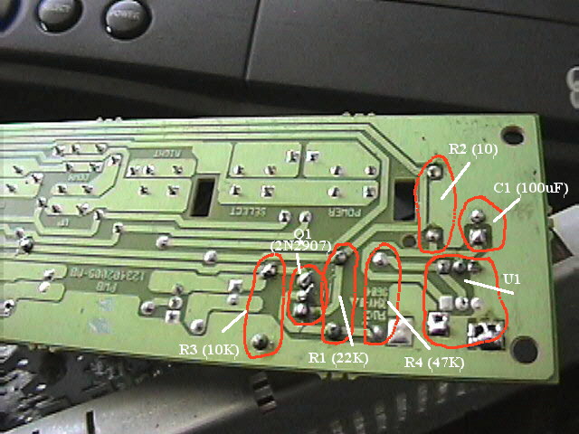
There is a 10k-ohm resistor that is installed on some boards and not on others. This is R3 on style A boards. If your board doesn’t have this resistor, you will need to install one.Resistor identification by Color Bands:
| Resistance | 1st band (1st number) |
2nd band (2nd number) |
3rd band (multiplier) |
4th band (tolerance) |
| 47k ohm | yellow (4) | violet (7) | orange (x1000) | see below |
| 22k ohm | red (2) | red (2) | orange (x1000) | see below |
| 10k ohm | brown (1) | black (0) | orange (x1000) | see below |
| 10 ohm | brown (1) | black (0) | black (x1) | see below |
Resistor Tolerance (fourth band):None +/- 20%
Silver: +/- 10%
Gold: +/- 5% (standard, 5% or better recommended for upfit)
Red: +/- 2%
Installing the components:
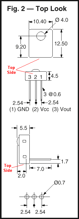
U1 is a 3 pin device with an IR phototransistor and op-amp / comparator circuit hooked together to deliver a TTL waveform representation of the infrared light pulses striking the phototransistor. (If you care.) The 3 pins are Vcc (+5V), Gnd, and Vout (Data Out). Echostar uses a U1 that has Vcc in the middle and Gnd on the left (looking from the front of the board). Make sure you know the pinout of your U1 before installing it; you may have to do a little creative lead-bending. The signals should be the same; only the placement may differ. On the circuit board, Vcc is the trace that connects to the 10 ohm resistor. Gnd connects directly to the ground plane. Vout goes to the 47k resistor. Generally, IR receiver modules have some sort of a metal shielding surrounding them. Be cautioned, removing the shielding can greatly reduce the IR receiver range. To locate the ground pin, measure resistance between the metal box and the 3 pins; the Gnd pin will read will read 0 ohms resistance. Once you’ve found Gnd, you can safely distinguish the Vcc and Vout pins by trial-and-error.
The IR receiver from Allcorp has a 5-foot cable leading from the module (shown in the photo above) to a stereo mini-plug. Cut and strip the cable near the mini-plug connector to expose the 3 wires inside. The red wire is Vout, the black (or sometimes white) wire is Vcc, and the bare/shielding wire is Gnd. (If you leave the mini-plug attached, Vcc goes to the tip of the mini-plug, Vout goes to the center band, and Gnd goes to the bottom band nearest the cable.)The IR receiver from Jameco has Vcc on the left, Gnd in the center, and Vout on the right, when looked at from the front, turned so that the leads are on the upper edge. Vcc and Gnd will have to be switched by doing a little bending.
The IR receiver from DigiKey has the pins in the proper orientation with Gnd on the left, Vcc in the middle, and Vout on the right. You will need to check that the eye lines up with the hole on the front cover; you may need to bend the receiver a little bit.
Outlines of the components are silk-screened on the top of the circuit board, so the orientation of sensitive components like the capacitor and the transistor shouldn’t be a problem. The board has holes and solder for the necessary components, all you need to add is the parts. Capacitor C1 is mounted with the negative strip facing upwards on board Style A; the negative pin goes to ground. Be sure to mount the capacitor close against the board; otherwise it will be too tall and push against the front cover after reassembly.
The board is wave-soldered, so you can either heat the existing solder and push leads through one at a time (easiest) or remove the solder from the holes and re-solder the components. There are 2 mounting locations for U1, with the one on the left being the primary location and the one on the right being the alternate. The Style A board, with all components installed, is shown below.
Once you’ve installed the components and checked thoroughly for shorts, opens, lost contact lenses, etc., plug the front panel into the motherboard, insert your smart card, hook up the antenna and TV out wiring, make sure the back of the front panel board isn’t shorting against the metal frame, and power up. If all goes well, you are ready to activate the IR circuit (4000 and lower models only).
When snapping the circuit board back into the front panel, make sure the lens or window on the IR receiver module lines up properly with the cone-shaped window (style B) or the hole above the power LED (style A) provided for it. A mis-aligned receiver can cause diminished range or no response at all. Also make sure you clipped all leads off roughly to the length of those of the preexisting components. Leads too long can short against the metal frame after reassembly.
Test the remote control before reassembling the receiver.
Circuit Diagrams Notes:
In case there is yet another unknown board style out there, here are 2 representations of the circuit you are rebuilding. The component designations below (R1, C1, etc.) are for Style A boards. If you have a different style of board, you will need to determine the appropriate component designations.
Gnd _____/-_____
| _____________________ | IR | U1
/ |Vout_Vcc_Gnd|
10k/ ___|B__PN2907 R1 | R4 | | |_______
R3 _____/ ____///____|__///________| | |
| C| |E | 22k 47k | |
| | | | R2 | + - |
|___| |_____|_________________________///____|—-|(—–|
| | 10 100uF |
_________Out +5v C1 Gnd
(Cable pin#) (10) (2) (1)
Programming Receiver:
(NOTE: Model 5000 and most 2000 receivers do not require this programming)To tell the satellite receiver to look for an IR signal, you will need to activate IR in the satellite receiver software. The UHF portion of the remote will continue to operate as normal, you’re just adding the IR. Using your UHF remote (or front panel buttons on the receiver), power on the receiver and enter the following key sequence:
Menu
6 (”System Setup” menu item)
1 (”Installation” menu item)
3 (”System Info” menu item)
This will bring you to a screen showing specific system info. From this screen, you will activate the IR by pressing the following key sequence:
Info
Browse (Right arrow button)
Theme (Left arrow button)
The screen will redraw and the letters “IR” will appear next to the Remote Address number.
Programming Remote:
If you will be using a pre-programmed universal remote, make sure your remote address is set to 1. If you are using a programmable remote control, it can learn the codes from the original remote control for any remote address. To change the remote control address:
|
 |
Done. Your 4000 is now IR-capable. The same key sequence disables IR. A memory dump reset will also cause the receiver to revert to UHF-only.Reassemble the receiver and enjoy.
Universal Remotes:
- One-For-All universal remotes use code 775. The RCA Universal Custom 8 Remote uses code 0792. For both, be sure to set the satellite receiver to remote address 1. One For All also has codes for remote addresses 2 and 3: 1170 and 1171.
- Not all learning remotes can actually learn the 57 kHz carrier frequency of the Dish remote control. Some recommended remotes, in order of increasing price, are:
- Radio Shack 15-2116 by One-For-All (learning, backlight, $30 at Radio Shack)
- Philips Pronto (mail-order, about $300)
- See my Universal Remote page for more details.
- I encourage you to investigate these and other remotes at RemoteCentral.com.
Oh no! I messed something up and it doesn’t work!:
If you are having problems with the upfit, the best way to check your component installation is to use a ohm meter to check the solder joints. If the meter has a continuity mode, use it and you will hear a beep when a circuit passes the continuity test.
- Place one cable of the ohm meter on a component lead
- Look at the back of the board and find another component on the same trace
- Put the cable of the ohm test lead on the lead of the second component. where the trace
- The resistance should be very low (less than 2 ohms). Remember, you are only checking the resistance of the solder connections, not of the component.
- Be sure to make good contact between the test cable of the ohm meter and the component lead; poor contact will give inaccurate (high) resistance values.
- Note: you also need to make sure you don’t have any short circuits between components. Make sure there isn’t continuity were there shouldn’t be.
- Make sure the components are in the proper orientation.
If you are unable to identify any problems, or if you did something stupid like short-out the front panel to the case while testing, there is one last option. It has worked just fine for me but proceed at your own risk; this isn’t exactly the intended circuit.
The output of the IR receiver and the output of the UHF receiver are the same type of signal. As long as the IR receiver has power (5 volts) and ground, the output should work properly. You will need a piece of wire that is about 18 inches long. Solder one end of the wire to the output (V out) lead of the IR receiver. Make sure the wire doesn’t touch the lead next to it on the IR receiver! Pull about 1-inch of insulation off of the other end of wire, double it over, twist it, and put some solder on it to keep it from unraveling and to add a little strength. Put this end of the wire in the center (black wire) connector where the UHF antenna attaches to the main board. Be careful to insert all of the exposed jumper wire into the connector. If there is even one strand of the jumper wire in contact with the 12V pin beside it in the connector, it can fail anything in the circuit. Be sure to twist the jumper wire tightly and carefully insert it into the connector. You do not have to enable IR option in the software when using this method; you should turn-off IR if you manually enabled it. You should now (again) have IR capability.
This is basically the same modification as is used on the JVC HM-DSR100u D-VHS unit. Be sure to read the JVC D-VHS Upfit Instructions before performing this upfit. Visit the JVD D-VHS Modifications page to see the detailed JVC D-VHS instructions.

![]()
Hi, I just wanted to thank you for posting your instructions for the Dish Network IR Upfit. I have a Dish 4000 receiver with a worn out RF remote. I wanted to be able to use the remote from my new Onkyo home theater system. I ordered the parts from DigiKey, including a small plastic box to mount the IR receiver with a shielded cable and mini plug, so I could keep my Dish receiver hidden and still use the remote. After following your very detailed directions, I programmed my remote, and everything worked beyond my expectations! You may be interested to know that this was my very first electronic project I have ever tackled. I have used a soldering iron, but never on a circuit board. Thanks again for your clear directions even a novice like me could follow. Jim
Like the other comment… I just wanted to thank you for taking the time to share your information. I also had a worn out rf remote and besides, I wanted to use my Harmony 880. THANKS again!!!!! 🙂
JeffR.
You seem to know quite a bit about the dish IR/RF remotes. I am looking for technical information about the RF remotes, specifically frequencies and exactly what is transmitted. Obviously, I would like to backward engineer this with the end goal of an RF blaster for the dish 322 receiver. If you have any information you think would be of assistance, I would appreciate your help.
Thank you,
Jerry Hale