
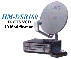
JVC HM-DSR100U IR Remote Control Modification
Overview:
This page contains instructions on how perform an InfraRed (IR) remote control upfit on the JVC HM-DSR100U D-VHS DishNetwork receiver. As shipped, the unit only receives Radio Frequency (RF / UHF) remote control commands, even though the Dish remote sends out both IR and UHF at the same time. This modification allows a universal remote to be used to control the receiver; eliminating the requirement to use the standard remote. The modified receiver will still work with the original UHF remote control as well as an IR remote control at the same time.Note: This modification works only on the the JVC HM-DSR100U D-VHS receiver. Please refer to the other section of my site to modify your DishNetwork / Echostar / HTS / JVC receivers based on the 4000, older 5000, or very old 2000 “deluxe” models.
If you are having trouble with UHF remote control reception, try relocating the antenna away from electronic equipment. This can be done by using piece of coax cable, preferably RG6, about 6 feet long.
Credits:
These instructions are based on a information posted by Bill Pherigo in the alt.dbs.echostar newsgroup. The post on which this page is based is archived at DejaNews at http://x8.dejanews.com/getdoc.xp?AN=435729052
Background:
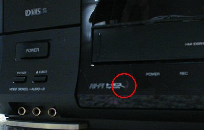
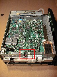
The HM-DSR100U actually contains an unused IR receiver, as shown in the following picture. When using the supplied remote control, the UHF signal is passed directly to the satellite half of the receiver, which passes commands on to the VCR half. The front panel buttons work in the opposite direction, they are first passed directly to the VCR half and then along to the satellite half. It would seem logical that the IR signals received on the front panel would also be passed along to the VCR and then to the satellite. But instead, the IR commands are ignored for some unknown reason.
Notes/Cautions:
- Don’t perform this modification unless you are somewhat comfortable with electronics
- Doing this will double plus super extra void your warranty — unless you un-perform the modification prior to sending the unit in for servicing.
- If you blow something up, don’t blame me. It works on mine. That’s all I can say.
- I don’t have any schematics.
- IR is an unsupported function on this unit but is not software activated; this means that the chances of this modification not working in the future due to a DishNetwork software upgrade are very, very slim — but anything is possible.
- I am in no way affiliated with Echostar or JVC. I am simply a customer who needed this function in my particular setup and had the information on how to do the modification.
- Read this through at least once before doing anything.
- Make sure the receiver is powered off, unplugged, card removed, etc.
Necessary tools and parts:
-
- Phillips screwdriver
- Wire cutters
- Small diameter (24-gauge) wire, about 2-feet worth to be safe
- Electrical tape
- Optional: Soldering iron and solder (not recommended)
Disassembly:
The cover is held on by 2 philips screws on both the left and right sides as well as 3 philips screws on the back. Pay attention for reassemble — the three screws on the back are different from the 4 on the sides.Once all screws are out, push the lid horizontally toward the back of the unit and lift it up and off.
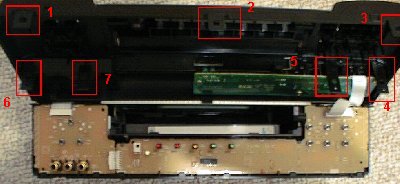
The plastic front panel snaps on/off via 7 plastic tabs. Remove the plastic front panel assembly by gently lifting the 7 plastic tabs one at a time and gently pulling forward. Be careful not to pull loose the white ribbon cable on the right side of the unit. If you do pull the ribbon cable out, you should be able to just push it back into the connector, but it’s better not to pull it out.
Start with tabs 1, 2, and 3, which are located on the bottom of the unit. Next loosen tabs 4 and 5 on the right side, then tab 6, and finally the inner tab 7. For tab 7, it will be necessary to use a narrow screwdriver to gently raise the tab — it’s hidden by the smartcard prior to it’s removal. After loosening all of the tabs, the front panel can be rotated upwards and sit on the top of the receiver, as shown below.
Installing the components:
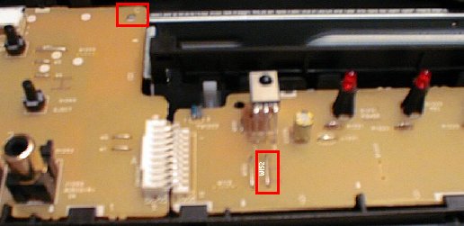
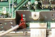
Attach one end of the small diameter wire to the jumper wire labeled W152. This wire is located directly below the center wire of the IR receiver, as shown in the following picture. Attach the jumper wire by removing approximately 1-1/2 inches of insulation and wrapping the jumper wire around W152 several times from top to bottom. It may be necessary to gently lift W152 with a small screwdriver so that wires can be inserted between it and the circuit board — be careful not to break or otherwise loosen the wire. Finish securing the jumper wire by wrapping W152 with electrical tape.Be sure that you do not have any contact with jumper W151, which is just to the left. If you feel the need, you can solder the jumper wire to W152. If you decide to solder, be very careful. It is possible to over heat W152 and cause it to lose contact with the circuit board. If you decide to solder anyway, melt the solder first and drop a bead off of the tip of the soldering iron to prevent over heating the wire.
Now you need to route the other end of the wire back down the left side of the receiver, being sure to avoid the slot for the SmartCard. Routing the wire through the hole highlighted in the previous picture helps to keep it in place and out of the way. Continue routing the wire to the gray 3-wire connector from the UHF receiver, shown in the picture below. (Note: the receiver in the picture below has the silver interior cover removed. With the cover installed, you will not see the circuit board portion shown. It is not necessary to remove this interior cover!)
You will now need to cut the wire to length and strip off about 1/2″ of insulation. Double-over the bare part of the wire, twist it tightly, and and slip it into the top of the center connector shown in the picture below. Be sure that the wire makes good contact with the pin inside. The center connector has a black wire leading to it. It may be easier to remove the 3-pin connector before inserting the wire.
Be careful about inserting all of the exposed jumper wire into the connector. If there is even one strand of the jumper wire in contact with the 12V pin beside it in the connector, it can fail the IR receiver circuit. Be sure to twist the jumper wire tightly and carefully insert it into the connector.
It’s very difficult to incorrectly reinstall the 3-pin connector due to it’s shape; but just in case, the bare wire goes toward the back of the receiver and the red wire goes toward the front of the receiver.
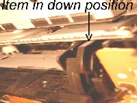
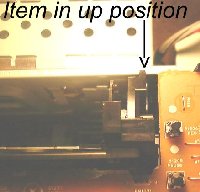
Now reassemble the receiver. There is a small mechanism located to the right of the cassette slot that needs to be in the down position when you reattach the plastic front panel assembly. It moves freely with the panel removed, and will be in the down position (by gravity) with the unit in its normal operating position. If in the up position when the front panel is reinstalled, the VCR door will not open!
Good:
Bad:
If you will be using a pre-programmed universal remote, make sure your remote address is set to 1. If you are using a programmable remote control, it can learn any of the codes for any of the remote address (1-15) from the original remote control. To change the remote control address:
- Switch the remote to the SAT mode
- Press the address button
- Press the 1 button (or the desired remote address, between 1 – 15, don’t put a 0 in front of single-digit addresses)
- Press the address button again to save the change to the remote control
- Make sure the satellite receiver is Powered-off, press the Info button
- Press the red Record button the the remote – the screen will update to show the new remote code
If you are using a OneForAll universal remote available at Wal-Mart stores, the code is 775. One For All also has codes for addresses 2 and 3: 1170 and 1171.
Notes:
Compared to the IR modification for other DishNetwork receivers, this one is pretty easy. I hope you enjoy your new IR-capable receiver!Plese comment me if I have left out anything and I will update this page; I would like for this information to be as accurate as possible. Also, let me know if you found this page helpful at all.
Fan Noise Modifications:
As many people have complained, the fan on the JVC HM-DSR100U DVHS receiver is quite loud. Three different levels of noise reduction solutions have been found and are listed below.
If you notice, the fan actually runs at 2 different speeds. When the receiver is first turned on, it runs at full speed for about 20 seconds. It then goes into a low speed mode that produces a pulsating sound about 4 time per second. The annoying sound quality of this low speed mode makes the fan noise even more of a problem.
Credits:
Thanks to Bob Kouré, Taylor Lyman, Irv Gleaner for their volunteered information.
Level 1: Remove Fan Shroud (very easy)
The easies way to reduce the fan noise of this unit is to remove the metal shroud and mesh that surround the fan. This case greatly amplifies the noise of the fan and may even rub against the fan.
Removing the shroud does expose the fan, allowing the back part of the blades to be touched by wondering fingers. The chances of injury are extremely low due to the limited fan torque, however, proceed at your own risk.
Level 2: Isolate Fan from Receiver (easy)
To further reduce the amount of fan noise, the fan can be physically isolated from the receiver using any type of flexible gasket material. I used a small piece of 1/8″ rubber band stuck under each corner of the fan. This does allow a small air leak around the sides but not enough to effect fan performance. An alternative is to use a soft foam material around the entire base of the fan.
Level 3: Replace Fan (difficult)
The stock fan is a Copal F412R 41×41.12.5mm, 5.3cfm, 23dB. A suitable replacement is a Rotron CRO412MB-G70 40×40x10mm, 4.7cfm, 17dB. This fan is available from www.newark.com – part # 91F7443.
There are 2 options for replacing the fan. The first is unscrewing the fan, cutting the leads, and soldering in the new fan leads. The second option is to disassemble the satellite receiver and replace the fan and the leads.
Option 1:
- remove the four screws holding the existing fan
- cut the leads off of the existing fan
- solder the leads to the new fan
- screw in the new fan
Option 2:
There are at least two versions of the HM-DSR; these instructions were written for one version but should be similar to the other(s).
First, remove the unit cover, unscrew the top module (just move it an inch or two aside), and unscrew the power supply. Push the power supply toward the front of the unit an inch or so and lift out. The plate the fan is mounted to comes off the power supply with three screws.
There’s a jam-wire connector to hold the fan wires. Use a jeweler’s screwdriver to loosen the side clips and move the jam portion (facing where the wires enter the block away from the block. The fan wires will just drop out (note which side is red before removing…) Now… there are some metal crosspieces on the mounting plate (where the air goes through). There’s close enough to the fan blades to cause some noise, so I cut ‘em and filed the hole smooth (with the plate nowhere near the power supply – so as not to get metal filings in the
unit). I then reassembled (reverse disassembly – no tricky bits, just a lot
of screws).
If you decide to perform this upgrade, I am in now way responsible for
anything you do to mess your system – or yourself – up!
Here are the specifications of the original JVC fan. The fan is manufactured by Copal Co. Limited of Japan under a license from Micronel. The following information is printed on the fan:
UC Fan
CD Brushless
F412R-12MB-27
DC 12V 7 1113
Information was formerly available on the Copal web site at:
http://www.copal-electronics.co.jp/prod_e/p24_e.htmland
http://www.widus.co.kr/hojin/hhojin/part_dept/partner/copal/p24_e.html
These sites give the following information:
F412R -M
Max Air Flow: 0.15 m3/min (5.3 CFM)
Max Static Pressure: 25.5 Pa (2.6 mm H20)
Noise: 23 dB(A)
Size: 41×41×12.2 mm
The Micronel fan on which the Copal fan is based is the F41MM. The F41MM has the following specifications:
Voltage range: 10.2 – 13.2 V
Nominal current (max): 80 mA
Nominal power (max): 0.96 W
Typical speed: 5,400 rpm
Flow rate (max): 175 l/min (6.18 CFM)
Static pressure difference: (28 Pa)
Acoustic Emission: 21 dB(A)
It appears that the Micronel F41MM fan is quieter and more efficient than the Copal fan and will offer some improvement in noise. 2 dB(A) is a big decrease in noise level, but they may be measuring differently between the 2 companies.
The other option is the Micronel F41LM. It has a lower flow rate of 4.4 CFM, which will slightly decrease cooling efficiency, but the acoustic emissions are only 14 dB(A). It’s not likely that the receiver will overheat if the F41LM fan is used but I haven’t verified this yet.
D-VHS Tapes
Having trouble finding D-VHS tapes for your JVC HM-DSR100U? You can use S-VHS tapes instead and still record digitally. Name-brand tapes are recommended. Also, you can buy both D-VHS and S-VHS tapes at TapeWarehouse.com.
If you really want to try to save money, you can take a standard VHS tape and drill a “S-VHS / D-VHS identifier hole” in the bottom of the casing. You will need to compare a standard tape with a S-VHS tape to determine the size and location. Test these tapes by recording unimportant programs. I had problems when using this method, but others have had success.
Playing the D-VHS Tapes in a different VCR
I received a tip from long-time owner Ali that a newer JVC HD JVC 10000HM model D-VHS VCR can play the tape recorded in a HM-DSR100U. What is more it has a FireWire output that allows copying portions of old tapes to an Apple Mac using the Virtual D-VHS program. All of this works fine, finding a program that can play back the MPEG2 video stream files has so far been unsuccessful.
Thanks so much, this is just what I needed. I have the circuit board knowledge but feel more comfortable with a tutorial.